UBR-1 Overview
This section details the key components of UBR-1, including the kinematics, sensors and software.
Kinematics
UBR-1 is a 13-dof mobile manipulator with a mobile base, arm, gripper, and pan-tilt head.
Terminology
The robot kinematics can be described using the concepts of joints, links, and frames. Each of these is defined and represented in code, as well as having a unique name. In general, a single joint will have an actuator and a transmission and will connect two links together. A link is a rigid body in the kinematic tree, and will have a coordinate frame, but not all frames are associated with links. There are also “fixed” joints, so some rigid bodies that could be considered one link are considered to be two links rigidly joined together. This is done mostly at locations where there is a physical interface between components.
- Link
A link is a rigid body within the robot. It generally has geometry to define visual and collision-space representations, has inertial properties, and has a name. The links for the UBR-1 are defined in the “URDF” description that can be found in the ubr1_description package.
- Frame
Frames are geometric entities that represent coordinate frames in space. Every link has an associated frame, but we also use frames to represent other things, such as the optical frame of a camera, the global map, or the location of a detected object. Frames are always defined relative to one another, and relationships and transformations between them are tracked using the tf package.
- Joint
Joints are considered part of the robot, and define the relationship between links. The joints for the UBR-1 are defined in the URDF description that can be found in the ubr1_description package. The UBR-1 has mostly rotational joints, but the torso and gripper translational, and there are also a number of “fixed” joints used to represent the notion that two links are part of the same rigid body. Rotational and translational joints are generally represented in the same way in the system, and we refer to joint “effort” instead of force or torque, as well as using position, and velocity to represent both linear and angular movement.
In general, the names for a link and the associated frame will be similar (e.g. forearm_link and forearm_frame), and the names the associated joint will be similar (e.g elbow_flex_joint).
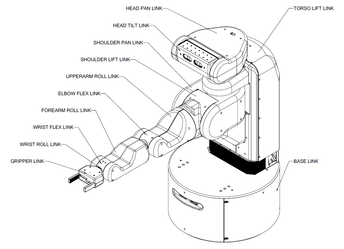
Figure 1: UBR-1 link names.
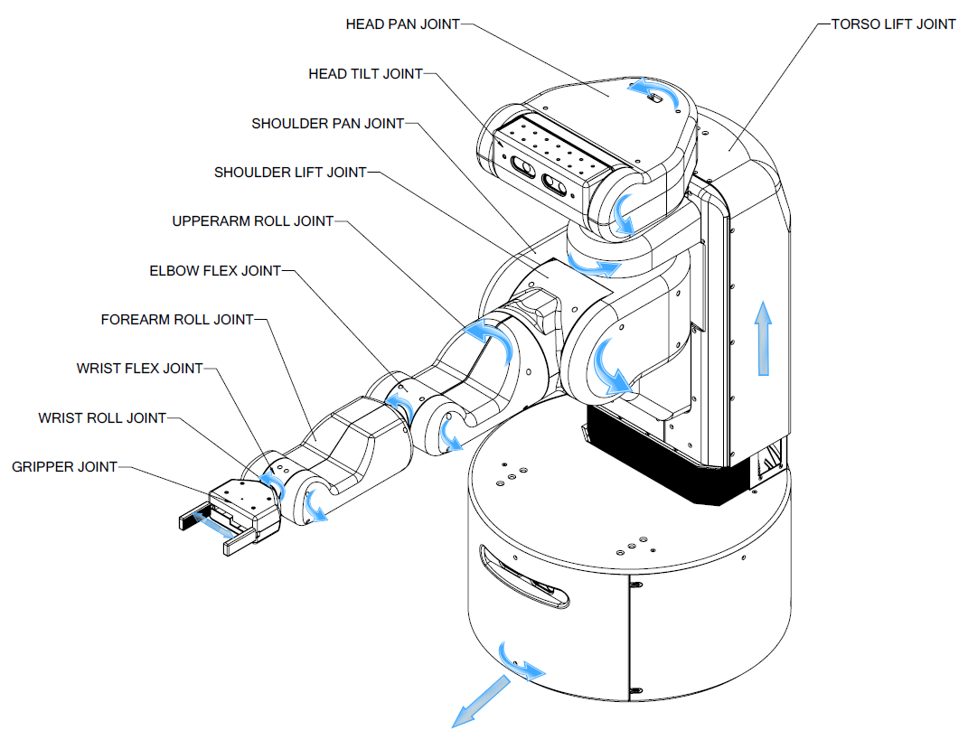
Figure 2: UBR-1 joint names and direction of positive motion.
Home Pose
In order to describe the UBR-1 robot pose and joint positions in a consistent manner, a home pose of the robot has been defined. At the home pose, all joint-angles are considered to be at zero. In the home pose the arm is straight ahead in front of the body, the gripper is closed, and the head is centered and level.
UBR-1 Coordinate System
The coordinate frames for all links of the UBR-1 are defined to be aligned with a world coordinate frame of positive z-axis up, positive x-axis forward, and positive y-axis robot-left when the UBR-1 is in the home pose. All joint angle conventions are chosen so that at the home position, positive motion of the joint causes positive motion around one of the positive axes of the joint coordinate system, as shown in Figure 2.
Sensors
This robot has a lot of sensors. They measure things, like awesomness.
- joint measurements
- head camera
- base laser
- imu in base
- imu in gripper
- awesome sensor
Software
TODO: link to ROS.org for the various tools UBR-1 is controlled through the Robot Operating System (ROS). ROS offers a number of capabilities that ease robot application development. These include things like a build system, command line tools (rostopic), visual tools (rviz), tutorials, and robot related software for things like processing camera data (opencv) or solving kinematics problems (orocos-kdl). However, the single greatest thing that ROS offers, is a large community and standard interfaces so that developers can share code. UBR-1 implements these standard interfaces:
TODO: for each of these, link to appropriate section of docs here on wiki (for the robot component) and on ROS.org (for the message type).
- The base is controlled through a geometry_msgs/Twist
- The arm is controlled via control_msgs/FollowJointTrajectoryAction
- The head can be controlled through the joint trajectory action, or via a control_msgs/PointHeadAction
- The gripper uses a control_msgs/GripperAction
- The head camera outputs sensor_msgs/Image and sensor_msgs/PointCloud2 topics.
- The base laser outputs sensor_msgs/LaserScan topics.
- The IMUs output sensor_msgs/Imu topics.
Since ROS developers can use standard interfaces, they can easily release code for a broader community to try. ROS consists of many software packages, most of which are listed on the ROS.org wiki.